01 / Bench results
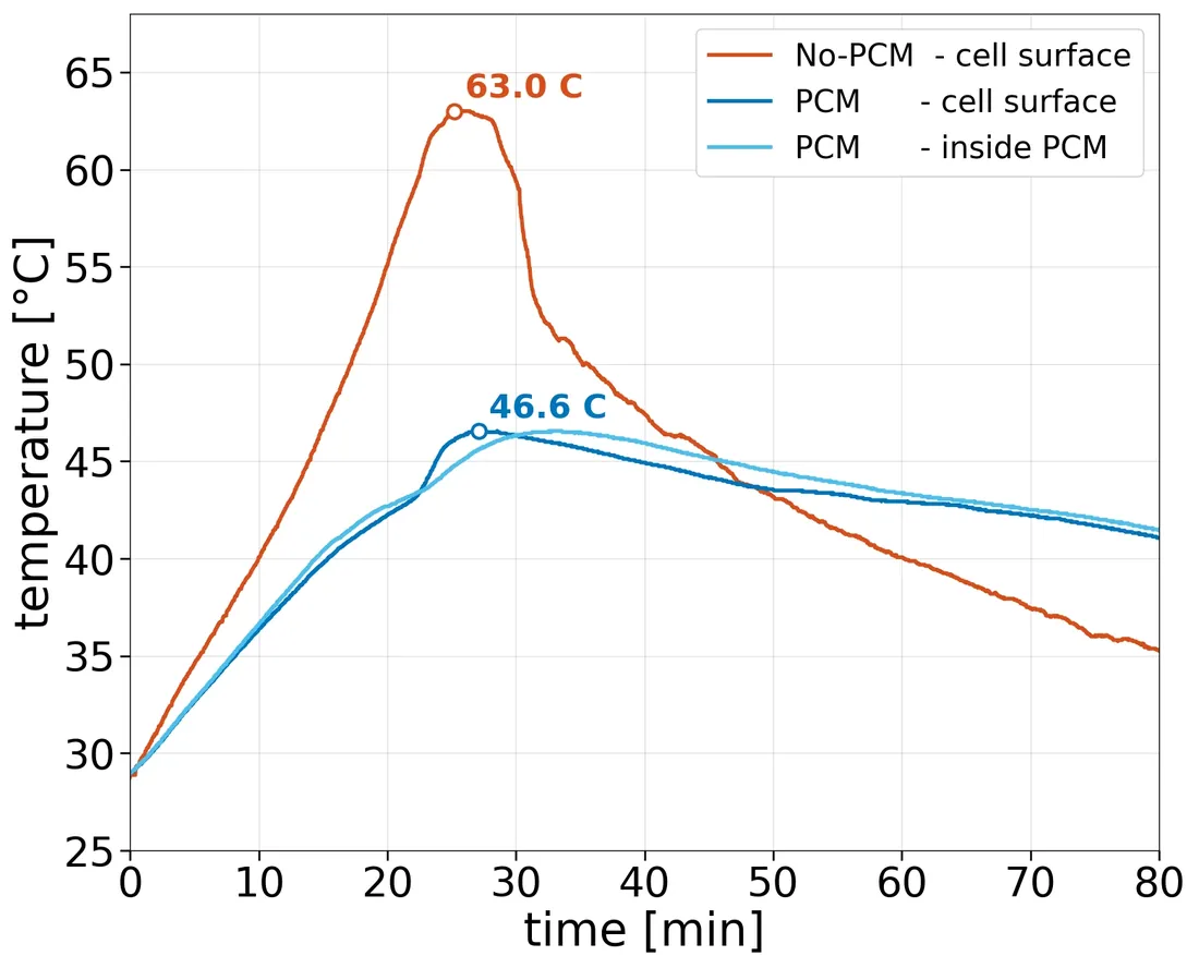
A 16.4 °C lower
measured peak.
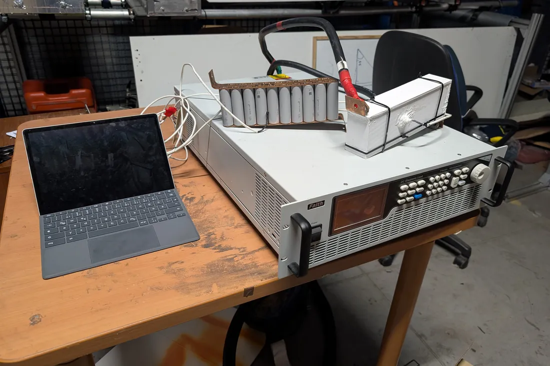
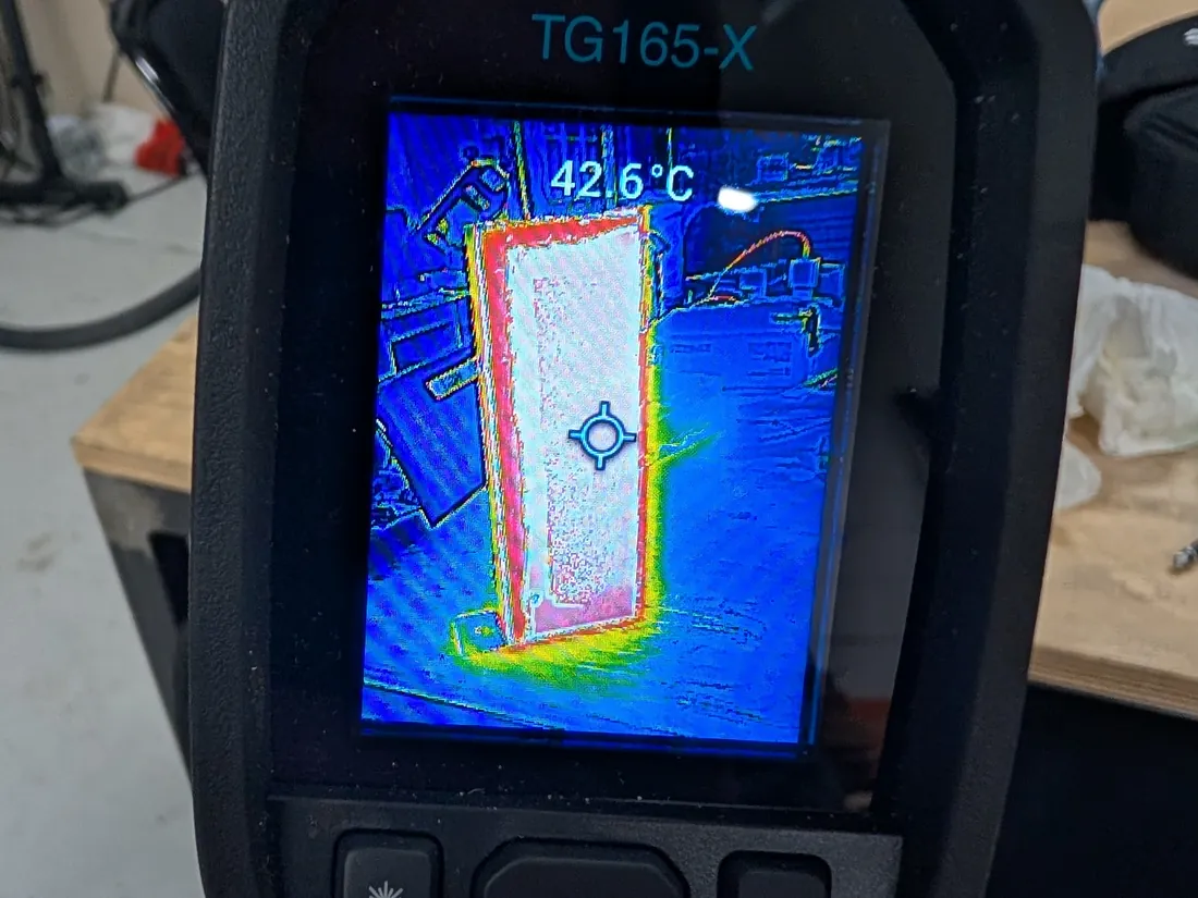
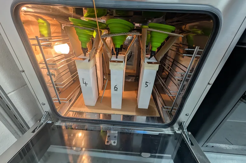
Two 19P modules, one with PCM and one without, discharged continuously at 240 A.
- Discharge
- 240 A, about 2.5C
- Ambient
- 28.0–28.5 °C
- Recovery
- About 3 hours
The 16.4 °C difference applies to this test setup; other loads and ambients need their own measurements.
02 / Specifications
The pack.
Nominal values of the demonstrator pack.
| Nominal energy | 9.918 kWhNominal. |
|---|---|
| Nominal voltage | 104.4 V29 modules in series. |
| Nominal capacity | 95 Ah19 cells in parallel per module. |
| Pack mass | 52 kg |
| Specific energy | 190 Wh/kg |
| Volumetric energy density | 385 Wh/L |
| PCM transition | 48 °CMaterial transition, not a cell-temperature ceiling. |
| Discharge rating | 3C / 8C peakPeak duration to be qualified per application. |
| Power rating | 30 kW / 80 kW peak |
| Operating voltage window | 72.5–121.8 VFrom cell limits of 2.5–4.2 V. |
| Configuration | 29S × 19PCylindrical 21700 Li-ion cells. |
| Cell | Tenpower INR21700-50XG |
|---|---|
| Chemistry and format | Li-ion, 21700 cylindrical |
| Nominal capacity | 5,000 mAh (minimum 4,950 mAh) |
| Nominal voltage | 3.6 V |
| Charge / cut-off voltage | 4.2 V / 2.5 V |
| Maximum continuous discharge | 40 A (90 A with 75 °C cut-off) |
| Internal impedance | ≤ 4 mΩ at 1 kHz, 30% SOC |
| Cell mass | 75 g maximum |
| Battery management | ANT smart BMS |
|---|---|
| Series support | 21S–30S programmable, configured 29S |
| Cell balancing | Passive, 180 mA |
| Protection | Short-circuit, over-current, temperature, over- and under-voltage |
| Temperature sensing | 4 sensors, −40 to 125 °C |
| Metering and communication | Coulomb counter; CAN, RS485, TTL, Bluetooth |
03 / Architecture
A thermal buffer inside a serviceable module
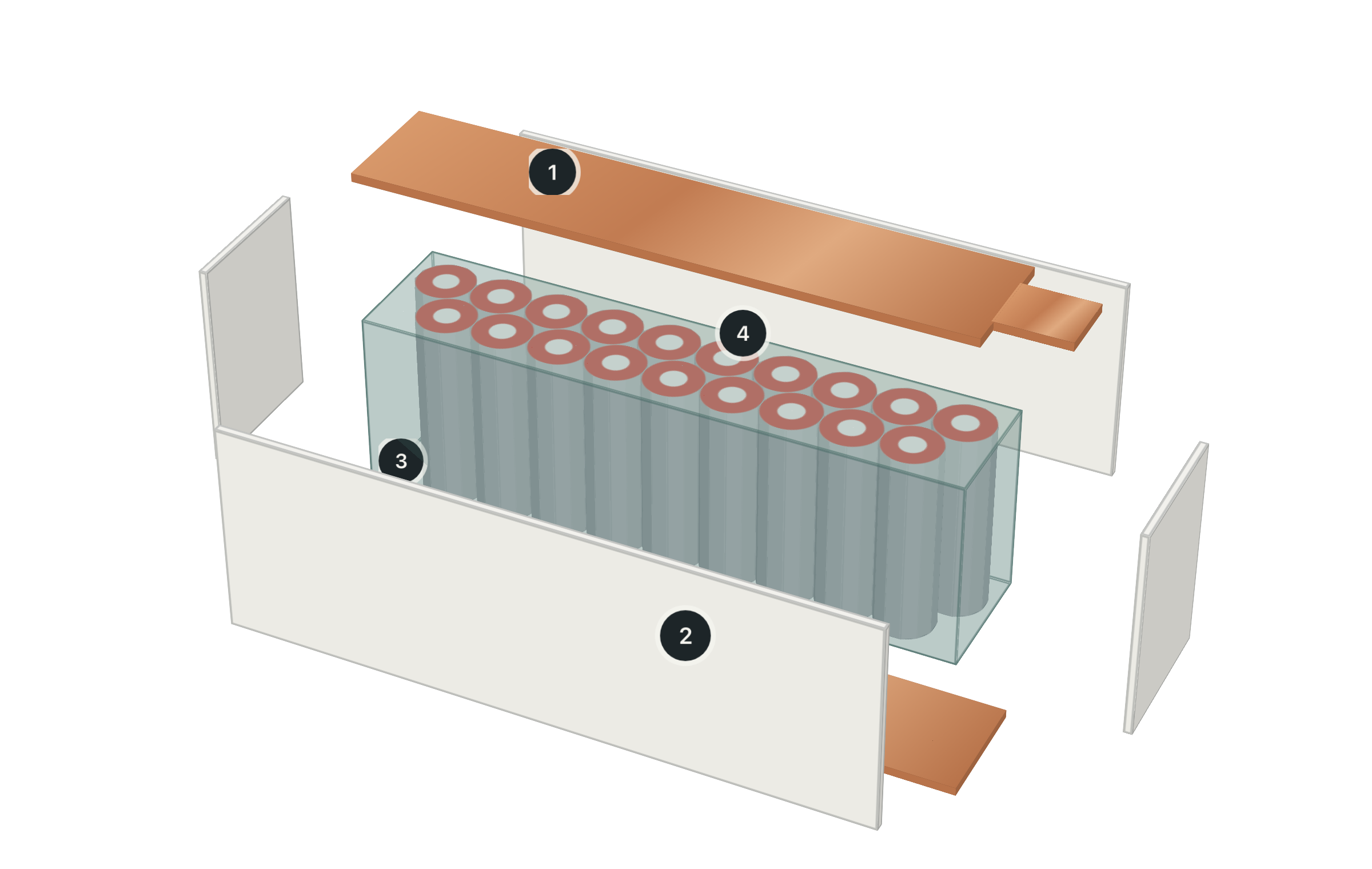
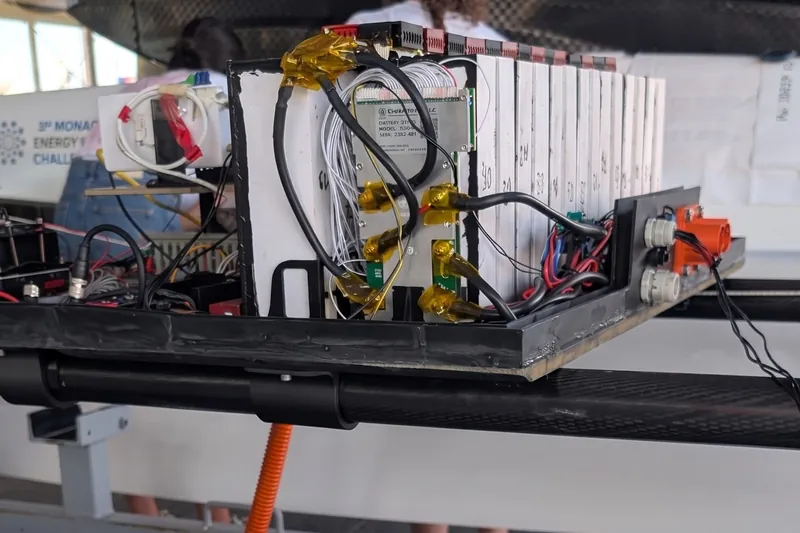
PCM-CAGE combines cylindrical cells, copper collectors and phase change material in a sealed, replaceable module. As the material melts it absorbs peak heat right next to the cells, with no dedicated fans or pumps in the module. The installation still needs a path through which that heat can leave.
- 129 PCM-CAGE modulesIn series, 104.4 V nominal.
- 2Copper busbarsLink one stage to the next.
- 3Smart BMSBalancing, protection, sensing.
04 / Material
The material: PCM48
The modules use PCM48, a bio-based, non-paraffinic phase change material with a transition around 48 °C, poured in as a liquid so it settles around every cell. Recent work comparing 42, 47 and 57 °C materials found 47 °C the most balanced, supporting this choice. Lot-specific calorimetry, conductivity and insulation tests are the next step.
05 / Operation
The duty cycle includes cooling down
The buffer is finite: once the material has melted, the benefit changes, so 48 °C is not a ceiling on cell temperature. After the bench discharge, full thermal recovery took about three hours. Mission, recharge and recovery are therefore designed as one sequence.
06 / Field demonstration
From the bench to the water
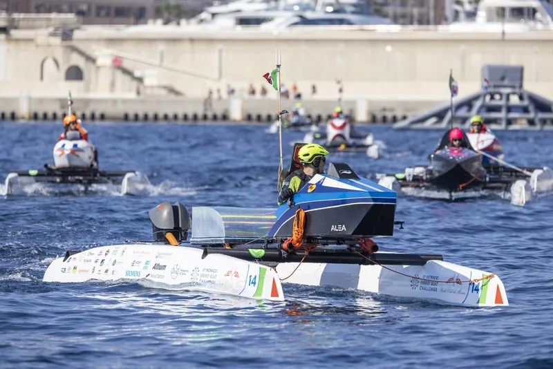
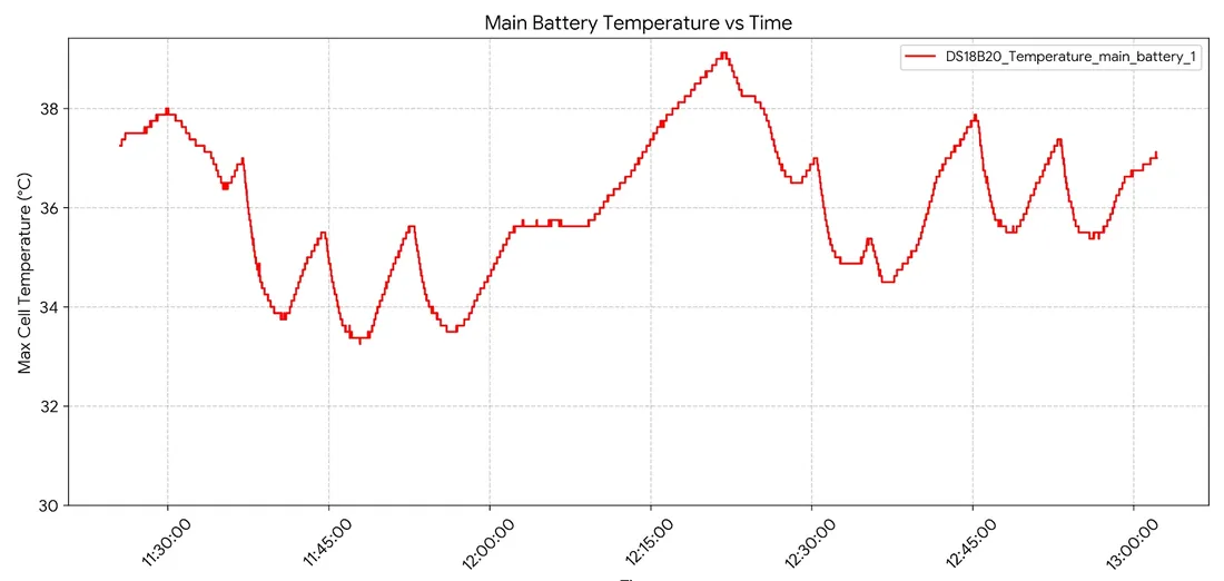
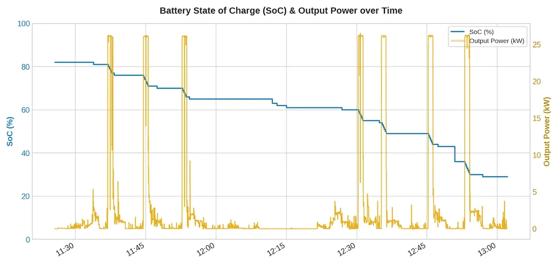
The complete 9.918 kWh pack was installed in a zero-emission racing catamaran for field trials in 2026, logging cell temperature, state of charge and power on the water. An Italian patent application for the architecture was filed in July 2026.
07 / Durability
Lower thermal stress can support battery life
Published experiments link PCM cooling to slower degradation: one study reports 14% longer cycle life at high discharge rates, another about 81% capacity retained with PCM versus 76% without after 600 cycles. Their cells and protocols differ from ours, and cooler is not always better for every chemistry. A lifespan figure for PCM-CAGE will come from matched aging tests.
08 / Charging
Charging is an electrical and thermal qualification
A thermal buffer can help sustain charge current where temperature would otherwise force derating, but it does not change the cell's approved limits. Charge rate is qualified together with the charger, BMS and the next mission, so no fast-charge time is claimed yet.
09 / System design
Energy density belongs to the complete system
The pack is rated at 190 Wh/kg and 385 Wh/L. PCM adds mass and volume, so fair comparisons include every component, from cells and containment to protection and cooling hardware.
10 / Research direction
Research points to better heat paths
The next gains come from better heat paths rather than more material: conductive structures, improved cell contact and transition temperatures matched to the charge protocol. Each must keep the composite electrically insulating.
11 / Development targets
Where the design is going
Provisional engineering objectives for the next iteration, to be achieved together on one product configuration.
| Metric | Today | Target | Stretch |
|---|---|---|---|
| Specific energyWhole-pack redesign, same energy. | 190 Wh/kg | ≥ 200 Wh/kg | ≥ 210 Wh/kg |
| Volumetric energy densityPackaging redesign, same boundary. | 385 Wh/L | ≥ 400 Wh/L | ≥ 425 Wh/L |
| Hottest instrumented cellAt about 2.5C, with ≤ 5 °C spread. | 46.6 °C peak surface, one module test | ≤ 50 °C | — |
| Dedicated cooling powerDuring passive operation. | No fans or pumps in the module | 0 W | — |
| Charging, 10–80% SOCWithin cell limits, with aging checks. | Not yet qualified | ≤ 50 min at up to 1C | ≤ 30 min at up to 2C |
| Submodule replacementAfter isolation and cooldown. | Replaceable by design | ≤ 15 min | — |
| Cycle life to 80% SOHMatched aging tests. Not a claim. | Not yet measured | Research hypothesis: +20% | — |
Targets, not results.
12 / Qualification
From prototype to industrial specification
Qualification starts from the customer's operating envelope: ambient, load, state of charge and recovery time. Repeated tests on representative assemblies then fix temperature limits, charging behaviour and readiness for the next mission.
Lead KPI
Useful mission energy, delivered repeatedly.
The useful electrical energy delivered at the requested power and within the qualified temperature window, including the next mission after the permitted turnaround.
- Peak cell temperature and spread over the full duty cycle
- Time to thermal readiness for the next mission
- Power and energy delivered before thermal derating
Primary sources / 2023–2026
References.
Published results guide development; they are not PCM-CAGE forecasts.
- Experimental Evaluation of Phase Change Materials on the Cooling Performance of Cylindrical Battery ModulesBatteries 12(9), 333
- Experimental investigation of the effect of phase change materials on the behavior of battery at high-rate discharge in electric toolsSustainable Energy Technologies and Assessments 58, 103330
- Numerical and Experimental Investigation of Phase Change Material-Based Thermal Management for Mitigating Aging in Lithium-Ion Battery PacksMetallurgical and Materials Engineering 31(4), 162–174
- Life-cycle models for high C-rate mid-format Li-ion battery packs as impacted by active heat transfer measuresJournal of Power Sources 648, 237363
- Electrochemical-thermal-aging coupling in Li-ion cell with composite phase change materialApplied Thermal Engineering 302, 131996
- Experimental Approach of Thermal Management Properties for Phase Change Materials in Energy Storage Modules at Different Power LoadingEnergy Storage 8(2), e70365
- Characterization of Cycle-Aged Commercial NMC and NCA Lithium-ion Cells: I. Temperature-Dependent DegradationJournal of The Electrochemical Society 170, 120538
- Thermal management properties of BN/paraffin/expanded graphite composite phase change materials for cylindrical 21700 Li-ion batteryThermal Science and Engineering Progress 70, 104516
- Passive thermal management of a Li-ion battery module using phase change materialsApplied Thermal Engineering 288, 129563
- Experimental Study of Temperature Control Based on Composite Phase Change Materials during Charging and Discharging of BatteryJournal of Thermal Science 33, 578–590
- All-climate battery thermal management system integrating units-assembled phase change material module with forced air convectionEnergy 294, 130642
- Experimental study on battery thermal management using low temperature solid-solid metal phase change materialInternational Journal of Heat and Mass Transfer 256, 127959
- Coordinated thermal management of prismatic battery packs using cascaded PCM-liquid cooling couplingEnergy 356, 141309
- Experimental and numerical analysis of a hybrid cooling concept for an electric battery moduleInternational Journal of Heat and Fluid Flow 106, 109320
- Thermal management of Li-ion battery based on honeycomb-structured fins-modified phase change materialInternational Journal of Heat and Mass Transfer 232, 125962
The next step
Define the operating envelope.
Tell us your load, ambient and turnaround, and we will assess the fit.